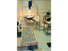
BR-PV-TBK Terminal Box Knockout Tester Implementation of standards: IEC 61730-2:2004 & Ed.2, VDE 0126-5:2008, EN 168
Mandrel: minimum 38mm long by 6.4 mm diameter Junction box fixture: adjustable Load force: 44.5N Mandrel and poise lifting: pneumatic control The test for hydrostatic test, must reduce or eliminate the drop impact force influenceing test results. Gas pressure method, adjustable speed, avoid the impact caused by direct terminal box knockout. Mandrel and pressure bar is separate, when mandrel pressure to junction box, mandrel and pressure bar separate, At this time knockouts force only mandrel add poise, have nothing to do with gas pressure. Attachment: ① Timer or mobile phone time ② Low temperature test chamber ③ Gap measurement and sharpness of edge determination
Purpose: Removable hole covers in the walls of module terminal enclosures (knockouts) shall remain in place under nominal force application and also be easily removed for the field application of permanent wiring system components. Condition: A sample of the polymeric terminal box with knockouts will be tested in an “as-received” condition at a 25°C ambient temperature. Another sample of the polymeric box is to be conditioned for 5h in air maintained at -20°C±1°C. The test shall be repeated on the box immediately following this conditioning. Procedure: The knockout shall be easily removed without leaving any sharp edges or causing any damage to the box. The procedure is as follows: Step 1 – A force of 44.5N shall be applied to a knockout for 1min by means of a mandrel, minimum 38mm long by 6.4 mm diameter, with a flat end. The force is to be applied in a direction perpendicular to the plane of the knockout and at the point most likely to cause movement. Wait 1 h and measure the displacement between the knockouts and the box. Step 2 – The knockout shall then be removed by means of a screwdriver, used as a chisel. The edge of a screwdriver blade may be run along the inside edge of the resulting opening once only, to remove any fragile tabs remaining along the edge. Step 3 – Repeat steps 1 and 2 on two additional knockouts. For a box employing multi-stage knockouts, there shall be no displacement of a larger stage when a smaller stage is removed. Pass criteria: The knockout shall remain in place after the application of the steady force and the clearance between the knockout and the opening shall not be more than 0.75 mm when measured. The knockout shall be easily removed without leaving any sharp edges or causing any damage to the box.