![]()
Features
|
Product Description |
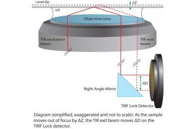
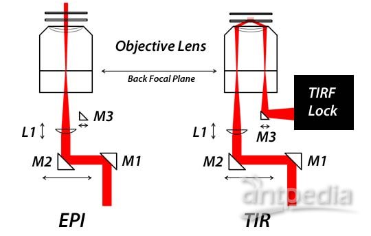
| After the user sets up TIR illumination and establishes the desired sample Z position, TIRF Lock™ keeps the sample in the focal plane by measuring the displacement of the exiting TIRF beam and maintaining that position via software feedback. The TIRF Lock™ system includes a quadrant photo-diode (QPD) head, a TIRF Lock™ controller, and a LabVIEW based VI. The TIRF Lock™ system is compatible with Mad City Labs RM21™ microscopes, the MicroMirror TIRF system, and the TIRF Module. |
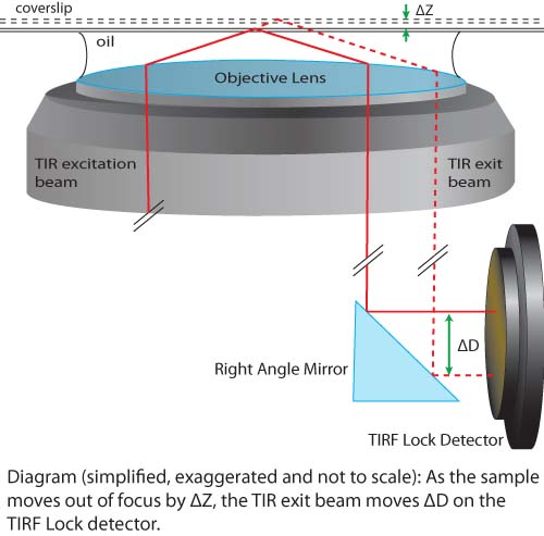 | 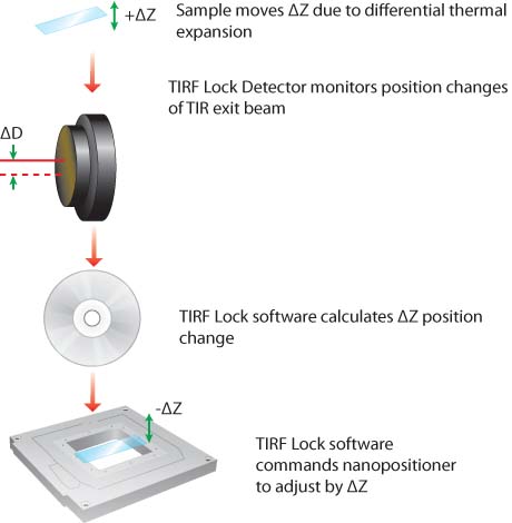 |
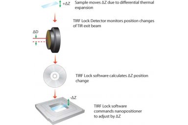
| As shown in the diagram above on the left, a small change in Z position of the sample due to differential thermal expansion in the microscope will result in a small change in position of the exit beam on the detector. The software uses that change in position to calculate an opposing change in the nanopositioner Z position, as shown in the schematic above on the right. |
Technical Specifications | |
| Detector Wavelength Range | 400nm-100nm |
| Detector Peak Responsivity | 0.4A/W @635nm |
| 0.67A/W @900nm | |
| Recommended Incident Beam Size | 300 µm to 1.5mmm |
| Sensor Size | 2.4mm x 2.4mm |
| Clear aperture diameter | 0.5 inches (1.25mm) |
| Aperture thread | SM05 (#0.535-40) |
| Detector head mounting thread | 8-32 or M4 |
| Mounting post holder thread | 1/4-20 or M6 (magnetic base and clamping fork provided) |
| Detector head cable length | 6 feet (1.83m) |
| Power supply | 90-260V |
| Controller dimensions | 8.375 x 3.5 x 12 inches |
| PC connections | USB 2.0 |
| Operating system compatibility | (32 or 64 bit) Windows XP Pro/Vista/7/Window 8 |
Related Products |
MCL-TIRF 对焦锁定器,TIRF Lock™
MCL-TIRF 对焦锁定器信息由北京欧兰科技发展有限公司为您提供,如您想了解更多关于MCL-TIRF 对焦锁定器报价、型号、参数等信息,欢迎来电或留言咨询。